ME218A is a Stanford class where you learn and apply complicated mechatronics. We learn about practical circuit design including motor drivers, microcontroller timers, and interrupts.
During this class, we conducted many labs and one final project. The topics of the labs are as follow:
- Drive a stepper motor
- Drive a DC motor (with an encoder) with PWM for speed control
- Create a basic robot that can identify and move towards a beacon emitting pulsed IR light
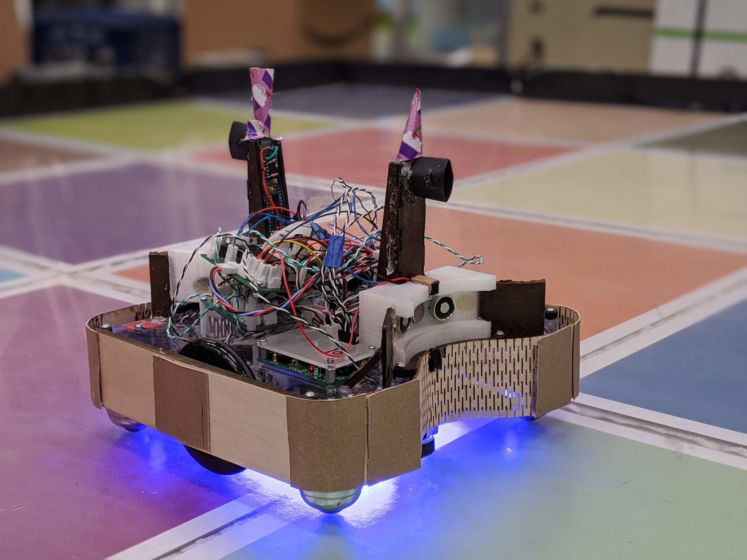
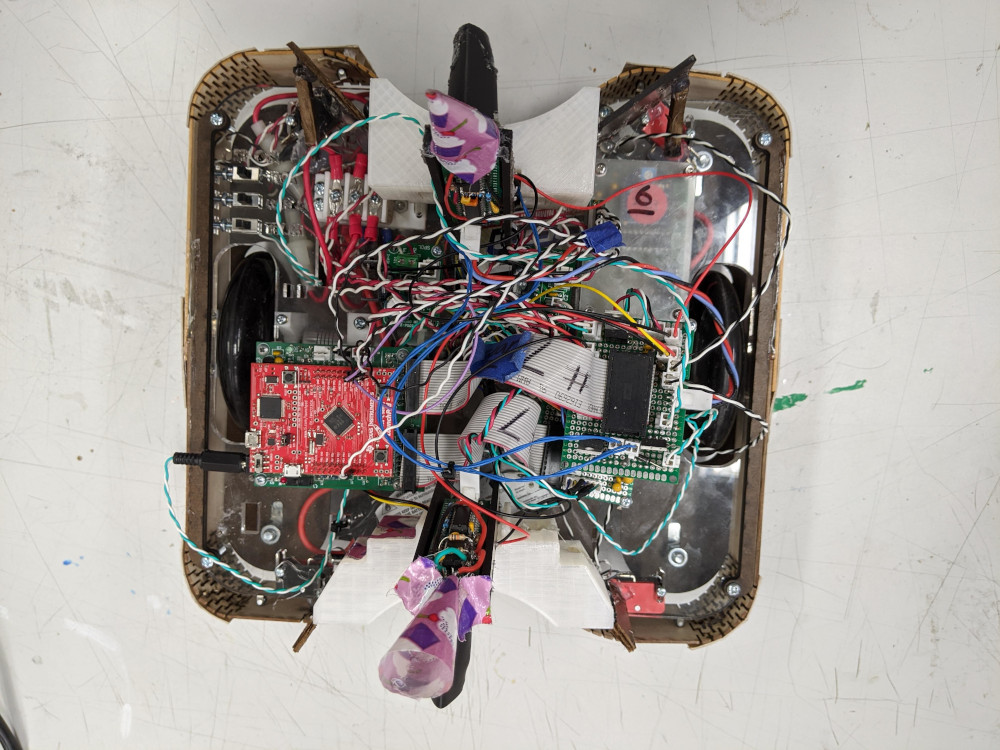
For the final project in the class, we had to create a robot that would autonomously compete in a game against robots made by the other students. We had to create a robot that would find “beacons” on a board and move them to our zone. Our robot, dubbed “Bobbithy”, has the following features.
- Two DC motors/encoders to drive the robot at controllable speeds
- Custom designed laser cut frame
- Two sets of IR detectors (front and back) to find beacons emitting a pulsed IR light source
- Electromagnet that can grab and move the beacons
- Color sensor to detect what area of the board the robot is in
- Accelerometer to detect what direction the robot is facing, since the board is tilted at 3 degrees
- A bumper with limit switches to detect contact
- Beam break sensors to detect when the robot is holding the beacon
Website dedicated to the project
This was a very difficult project due to the tremendous amount of features that needed to be implemented and that the robot had to function during the game with no human intervention. Our robot also had a nickname, “Mister steal yo miner”, since our robot was the only one that had the ability to steal beacons from the other teams (also known as Miners), while still being able to move our own beacons. This project was an incredibly rewarding experience and is where I learned the most of my mechatronics knowledge.
One circuit used in the project to read IR light coming from the beacons into the microcontroller as digital pulses. 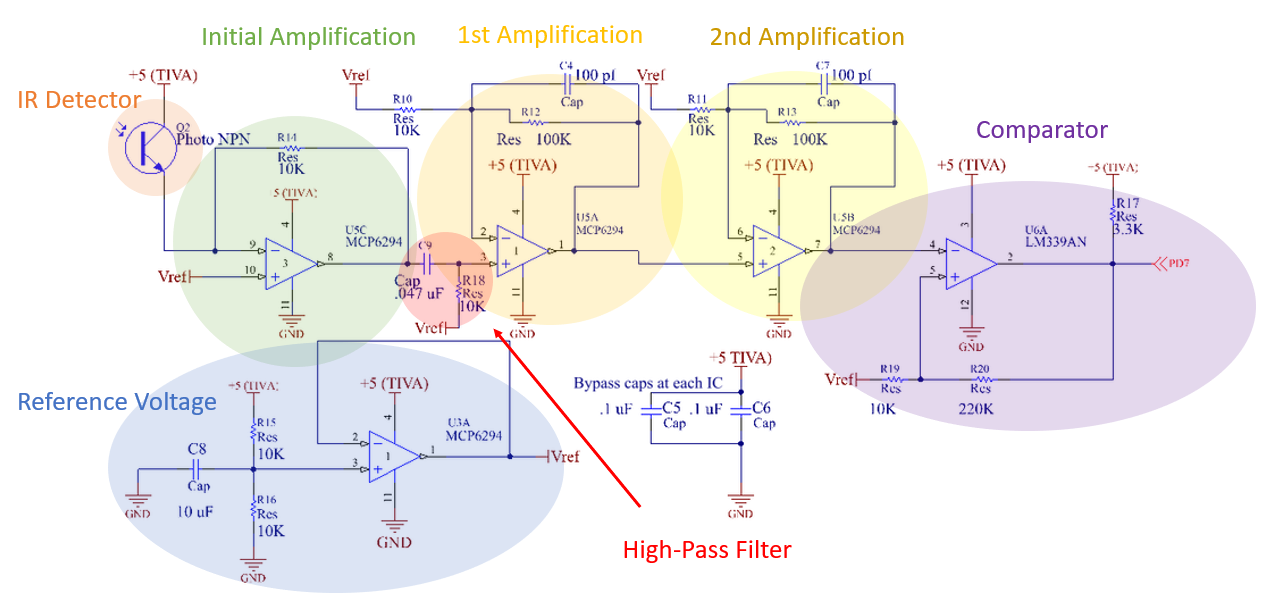
Coding excerpt used to initialize our accelerometer over SPI
static void InitAccelerometerISR(void)
{
  //Initialization code for interrupt service routine

  // start by enabling the clock to the timer (Timer 0)
  HWREG(SYSCTL_RCGCTIMER) |= SYSCTL_RCGCTIMER_R0 ;

  // enable the clock to Port F
  HWREG(SYSCTL_RCGCGPIO) |= SYSCTL_RCGCGPIO_R5;

  // since we added this Port F clock init, we can immediately start
  // into configuring the timer, no need for further delay
  // make sure that timers are disabled before configuring
  HWREG(TIMER0_BASE + TIMER_O_CTL) &= ~TIMER_CTL_TAEN;
  HWREG(TIMER0_BASE + TIMER_O_CTL) &= ~TIMER_CTL_TBEN;

  // set it up in 16bit wide (individual, not concatenated) mode
  HWREG(TIMER0_BASE + TIMER_O_CFG) = TIMER_CFG_16_BIT;

  // we want to use the full 16 bit count, so initialize the Interval Load
  // register to 0xffff.ffff (its default value :-)
  HWREG(TIMER0_BASE + TIMER_O_TAILR) = 0xffff;

  // Do not add a prescaler to the timer
  HWREG(TIMER0_BASE + TIMER_O_TAPR) = 0;

  // set up timer A and B in capture mode (TAMR=3, TAAMS = 0),
  // for edge time (TACMR = 1) and up-counting (TACDIR = 1)
  HWREG(TIMER0_BASE + TIMER_O_TAMR) =
      (HWREG(TIMER0_BASE + TIMER_O_TAMR) & ~TIMER_TAMR_TAAMS) | (TIMER_TAMR_TACDIR | TIMER_TAMR_TACMR | TIMER_TAMR_TAMR_CAP);
  HWREG(TIMER0_BASE + TIMER_O_TBMR) =
      (HWREG(TIMER0_BASE + TIMER_O_TBMR) & ~TIMER_TBMR_TBAMS) | (TIMER_TBMR_TBCDIR | TIMER_TBMR_TBCMR | TIMER_TBMR_TBMR_CAP);

  // To set the event to rising edge, we need to modify the TAEVENT/TBEVENT bits
  // in GPTMCTL. Falling edge = 01, so we set the TAEVENT/TBEVENT bits
  HWREG(TIMER0_BASE + TIMER_O_CTL) |= TIMER_CTL_TAEVENT_M & TIMER_CTL_TBEVENT_M;

  // Now Set up the port to do the capture (clock was enabled earlier)
  // start by setting the alternate function for Port F bit 1 (T0CCP1)
  HWREG(GPIO_PORTF_BASE + GPIO_O_AFSEL) |= BIT1HI;

  // Then, map bit 1s alternate functions to d T0CCP1
  // 7 is the mux value to select both wide timers
  HWREG(GPIO_PORTF_BASE + GPIO_O_PCTL) = (HWREG(GPIO_PORTF_BASE + GPIO_O_PCTL) & 0xffffff0f) + (7 << 1 * BITS_PER_NIBBLE);

  // Enable pins on Port F for digital I/O
  HWREG(GPIO_PORTF_BASE + GPIO_O_DEN) |= BIT1HI;
  // make pins on Port F into inputs
  HWREG(GPIO_PORTF_BASE + GPIO_O_DIR) &= BIT1LO;

  // back to the timer to enable a local capture interrupt
  HWREG(TIMER0_BASE + TIMER_O_IMR) |= TIMER_IMR_CAEIM | TIMER_IMR_CBEIM;

  // enable the Timer A and B interrupts in the NVIC
  // T0 Timer 0B is interrupt number 19 so appears in EN0 at bit 19
  HWREG(NVIC_EN0) |= BIT19HI;

  // make sure interrupts are enabled globally
  __enable_irq();

  // now kick the timers off by enabling them and enabling the timer to
  // stall while stopped by the debugger
  HWREG(TIMER0_BASE + TIMER_O_CTL) |= (TIMER_CTL_TAEN | TIMER_CTL_TASTALL) | (TIMER_CTL_TBEN | TIMER_CTL_TBSTALL);

  printf("Accelerometer ISR Initialized Successfully\r\n");
}